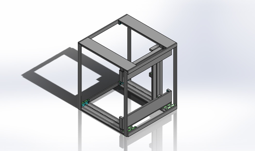
The aim of the design is to resemble the mechanism of a 3D printer with certain parts provided for building. The final simulation will be presented to print a cube shape.
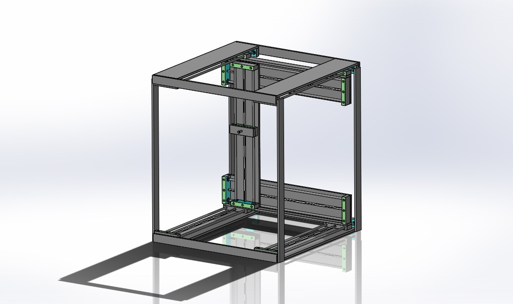
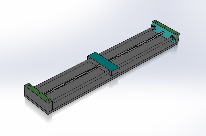
The design consists of three bars with motor inserted in each one as shown. The motor on each bar has its own 1-D motion. There is a thin plate on each motor to connect the bar in order for the 3D motion. On the bar that stands vertically, there is an extruder head.
7 Driving motor bars are used:
-2 on the bottom facing up
-2 on the top facing down
-2 attached on the other top and bottom ones facing front
-1 attached on the driving motor bars that are facing front
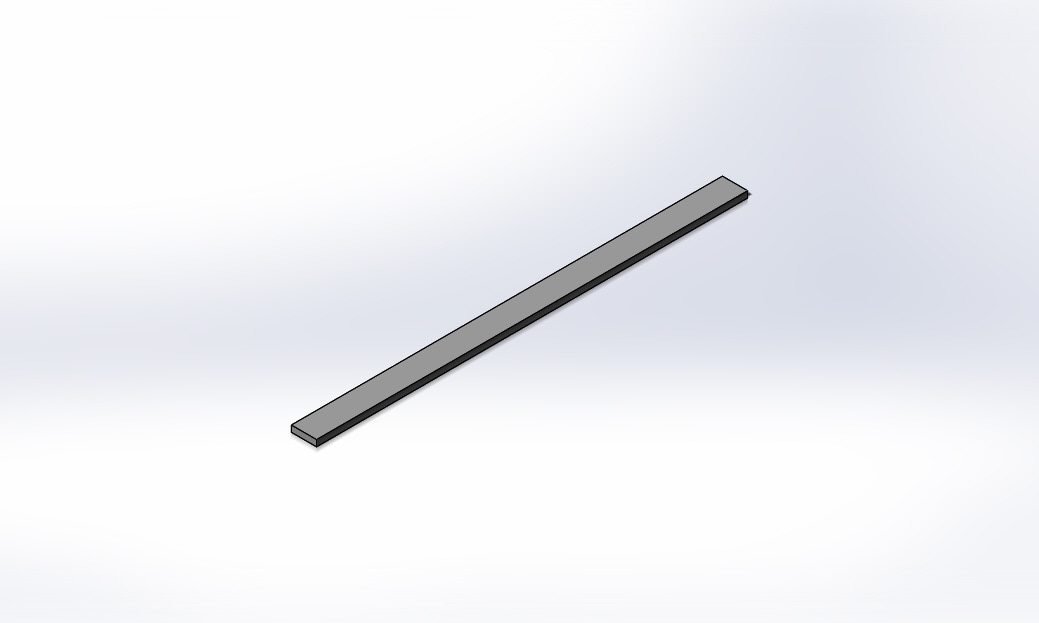
4 35-in supporting bars are used
-2 on the front side
-2 on the rear side
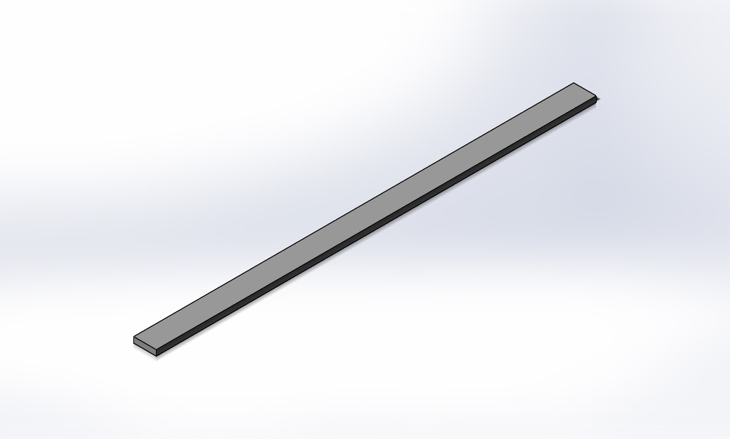
4 39-in supporting bars are used:
-2 on the right side
-2 on the left side
1 Extruder head is placed on the motor of the individual driving motor bar.
The design consists of three bars with motor inserted in each one as shown. The motor on each bar has its own 1-D motion. There is a thin plate on each motor to connect the bar in order for the 3D motion. On the bar that stands vertically, there is an extruder head.
7 Driving motor bars are used:
-2 on the bottom facing up
-2 on the top facing down
-2 attached on the other top and bottom ones facing front
-1 attached on the driving motor bars that are facing front
4 35-in supporting bars are used
-2 on the front side
-2 on the rear side
4 39-in supporting bars are used:
-2 on the right side
-2 on the left side
1 Extruder head is placed on the motor of the individual driving motor bar.
General View:
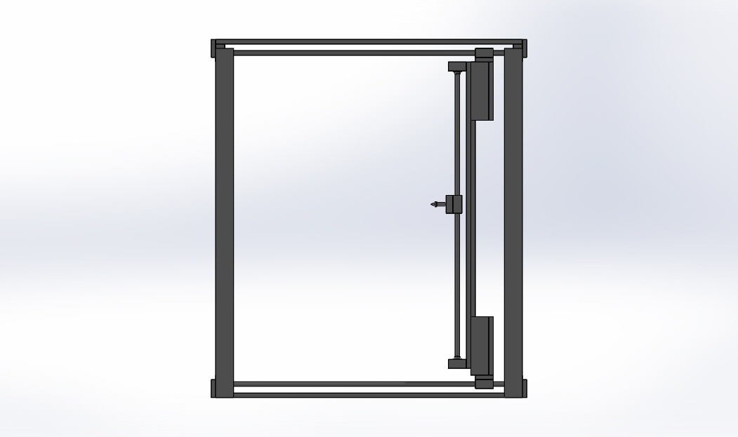
Right View:
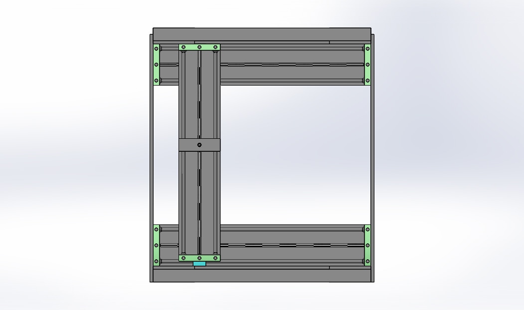
Front View:
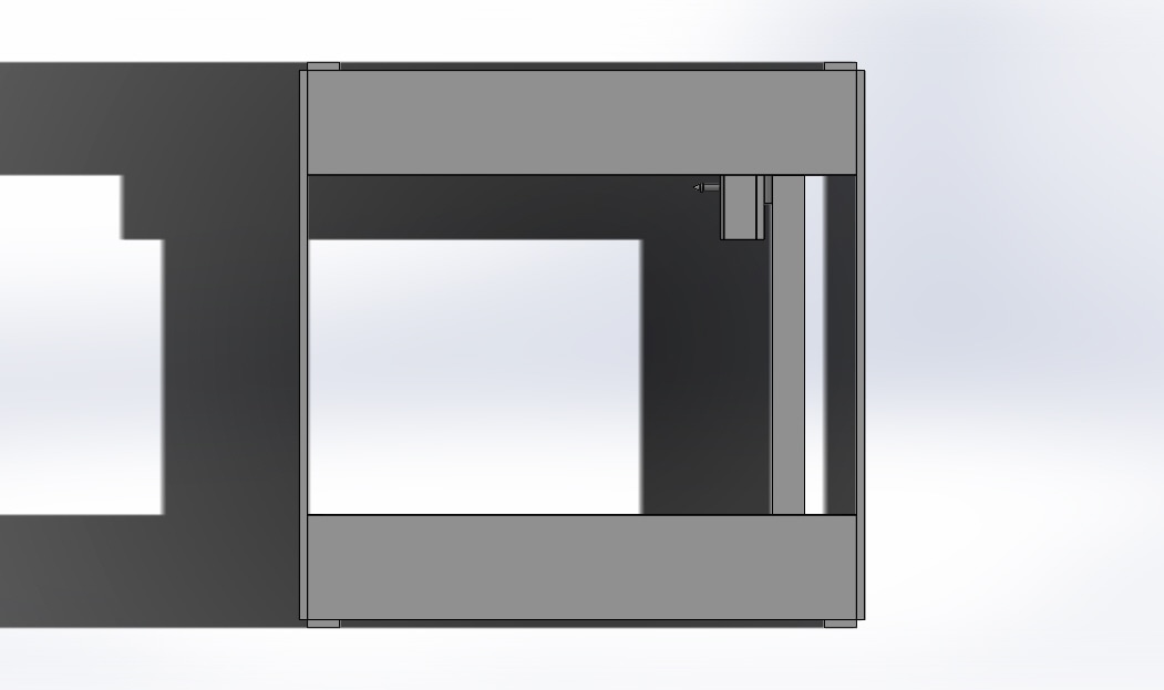
Top View:
General View (rear):
The components used in the assembly are shown below:

Performance Video: